DRILL DECOMPOSITION

DRILL DECOMPOSITION

DRILL DECOMPOSITION

TEARDOWN PROJECT

Spring 2025

TEARDOWN PROJECT

Spring 2025

CAD, Reverse Engineering, Manufacturing Design, Market Research

CAD, Reverse Engineering, Manufacturing Design, Market Research

SUMMARY

For my Engineering Design class I worked with a team of 2 others to teardown a drill. While we worked collaboratively for the project, my main responsibilities were the exploded view, function structure analysis, and CAD model.


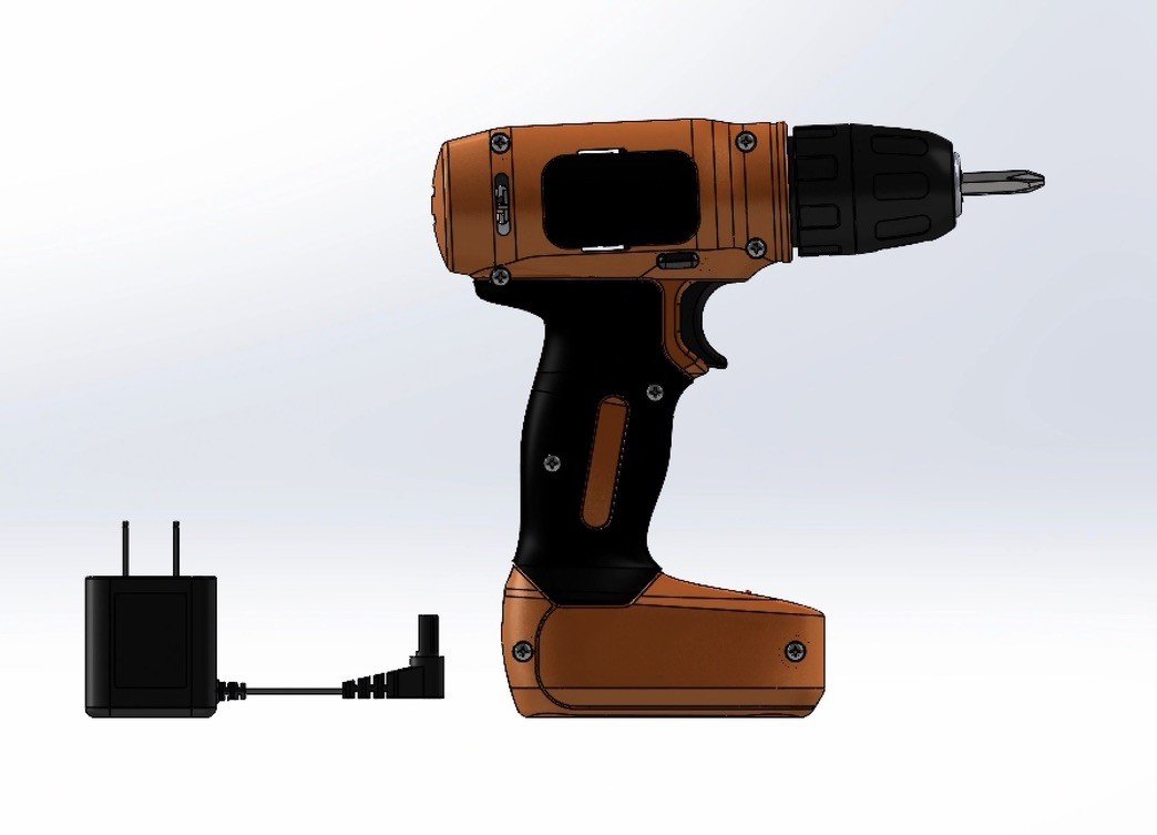
Within the CAD structure, I was responsible for the internals of the trigger structure and the outer case, which consumed the majority of my time. In addition to this I worked to assemble the full design, and create the digital exploded view. We were able to make the CAD model rotate using mates and worked to create the most photo-realistic design we could!

Partial view of drill final CAD

Partial view of drill final CAD

Drill exploded view

DESIGN ANALYSIS

I performed the physical teardown of the drill with one other member of my team. From this, I labelled, numbered, and cataloged each piece to prepare to create the exploded view. I wanted to preserve the mechanism flow of the drill in the layout, and placed the pieces to mimic the drill's shape, labelling them digitally. 

Drill exploded view

As part of our design analysis, we recorded our deconstruction and cataloged the process in steps. From this created a full decomposition table and a function structure diagram, which we broke down into multiple subsections, trying to capture the sub-assemblies specific inputs and outputs. We ended up with six subsections, a few of which had additional internal breakdowns.

As part of our design analysis, we recorded our deconstruction and cataloged the process in steps. From this created a full decomposition table and a function structure diagram, which we broke down into multiple subsections, trying to capture the sub-assemblies specific inputs and outputs. We ended up with six subsections, a few of which had additional internal breakdowns.

Final function structure diagram

Physical teardown process

Physical teardown process

CAD

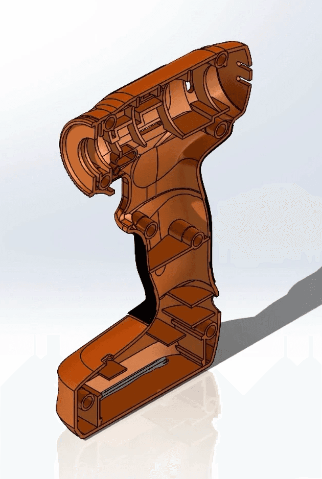
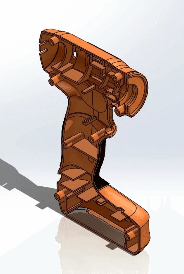
While my teammates worked on modeling the gears, motor, and chuck, I took on the switch, battery, and outer components. For these, my main focus became obtaining accurate measurements and deciding the most efficient and realistic way of modeling the organic shapes of the drill casing. The casing was by far the most elaborate individual item I have modeled, as I attempted to match the aesthetics and material changes.
FINAL ASSEMBLY

We were able to assemble each of our components together, which proved to bring a new set of difficulties as some pieces had slight measurement inconsistencies, causing them to intersect. I worked the interactions between the internal assemblies created by my peers with the case, adjusting and re-measuring as needed.

Case left inside view

Case right inside view

Case left inside view

Case right inside view

FINAL ASSEMBLY

We were able to assemble each of our components together, which proved to bring a new set of difficulties as some pieces had slight measurement inconsistencies, causing them to intersect. I worked the interactions between the internal assemblies created by my peers with the case, adjusting and re-measuring as needed.

In the end, our assembly had over 60 individual components including a spinning chuck and motor.

Trigger assembly

CAD exploded view

Final CAD assembly

Final CAD assembly interior view

Trigger assembly

CAD exploded view

Final CAD assembly

Final CAD assembly interior view

Create a free website with Framer, the website builder loved by startups, designers and agencies.